
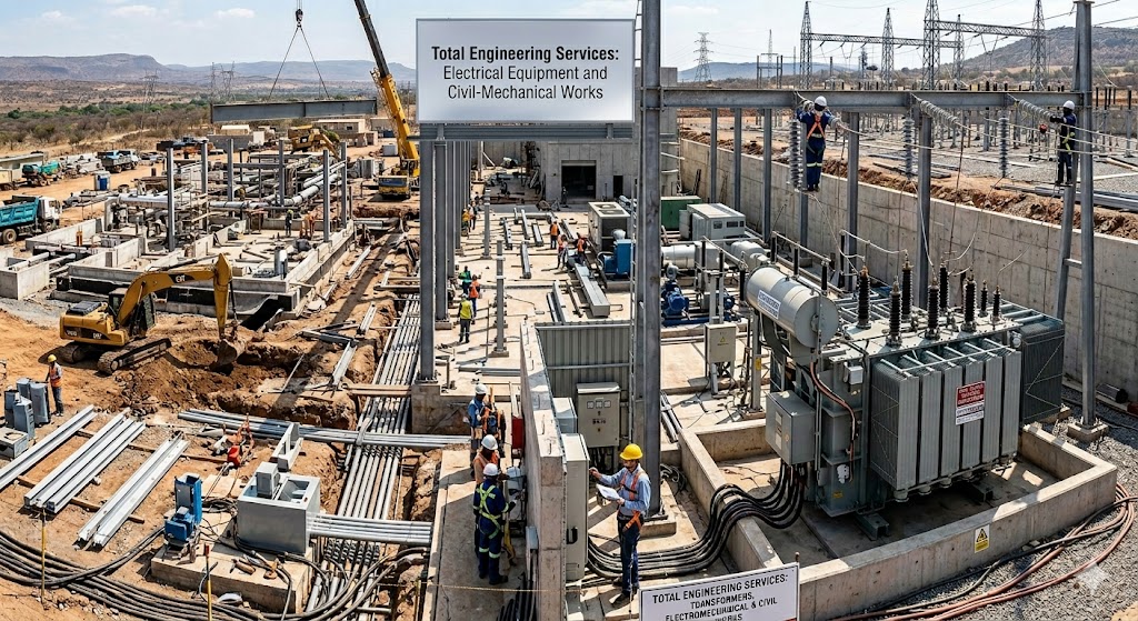
Total Engineering Services: Electrical Equipment and Civil-Mechanical Works
In the modern industrial landscape, the successful execution of large-scale projects—such as power substations, grid stations, and industrial complexes—demands a seamless integration of diverse engineering disciplines. The synergy between Electrical Equipment, Transformers, and Civil-Mechanical Works forms the backbone of resilient infrastructure.
When these elements are treated as a unified “Total Engineering Service,” the result is increased efficiency, reduced structural risks, and a longer lifecycle for critical assets. For more insights, read our article on Why Structural Integrity Saves Lives.
1. Electrical Power Systems: The Core of Operations
At the heart of any major power project lies the Transformer. As the primary apparatus for voltage regulation and distribution, its reliability is paramount for an uninterrupted power supply. Without properly specified transformers, the entire electrical network becomes vulnerable to failures, outages, and catastrophic damage.
Types of Power Transformers
Understanding the different types of transformers is essential for proper specification:
- Power Transformers (100MVA+): Used in transmission networks and large grid stations
- Distribution Transformers (up to 10MVA): Step-down voltage for industrial and residential use
- Instrument Transformers (CTs and PTs): For metering and protection systems
- Auto-Transformers: Economical for voltage transformation with a smaller size
Technical Specifications for Transformers
When specifying transformers for a 138kV grid station or industrial facility, the following parameters must be clearly defined:
| Parameter | Specification Range | Criticality |
|---|---|---|
| Voltage Ratio | 138kV / 13.8kV, 132kV / 11kV, 66kV / 11kV | High |
| Power Rating (MVA) | 10 MVA to 200 MVA | High |
| Cooling Type | ONAN, ONAF, OFAF, ODAF | High |
| Impedance (%) | 8% to 15% | Medium |
| Insulation Class | AA, A, B, F, H | High |
| Noise Level (dB) | < 65 dB at 1m | Medium |
Cooling Systems Explained (ONAN/ONAF)
The cooling system directly impacts transformer lifespan and loading capacity:
- ONAN (Oil Natural Air Natural): Self-cooled, suitable for moderate loads. No fans or pumps, making it reliable but limited in capacity.
- ONAF (Oil Natural Air Forced): Fans provide forced air cooling, increasing capacity by 30-40%.
- OFAF (Oil Forced Air Forced): Oil pumps and fans for maximum cooling, used in high-capacity transformers.
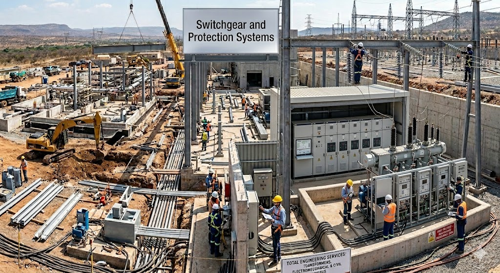
Switchgear and Protection Systems
Beyond the transformer unit itself, the integration of switchgear, circuit breakers, and protection relays ensures a fail-safe electrical network. Modern substations use:
- GIS (Gas Insulated Switchgear): Compact, reliable, suitable for urban areas
- AIS (Air Insulated Switchgear): Cost-effective, easier maintenance
- SF6 Circuit Breakers: High interrupting capacity, low maintenance
- Numerical Relays (IEC 61850): Digital protection with communication capabilities
Learn more about Grade-60 Steel Specifications for Transformer Foundations.
2. The Civil Perspective: Foundations for Power
Electrical equipment is only as stable as the ground it sits on. In high-voltage environments, civil engineering goes far beyond simple masonry — it requires specialized engineering design that accounts for static loads, dynamic forces, and environmental conditions.
Transformer Foundation Engineering
Transformers are heavy, vibrating masses that impose both static and dynamic loads on their foundations. A typical 50 MVA transformer weighs 80-120 tons, and during operation, it generates continuous vibration at 100-120 Hz.
Civil works for transformer foundations must include:
- Specialized reinforced concrete foundations designed to handle static loads while damping vibration transmission
- Oil containment systems — Integrated soak pits and bund walls that can contain 110% of the transformer’s oil volume (typically 30,000 to 60,000 liters)
- Seismic anchoring systems — Restraint mechanisms to prevent transformer movement during earthquakes, designed for peak ground acceleration of 0.3g to 0.5g, depending on the region
- Vibration isolation pads — Neoprene or spring isolators between the foundation and the transformer base
Cable Trenches and Conduits
Proper cable management is critical for safety and maintenance. Civil specifications must address:
- Dimensions: Standard cable trenches 900mm wide x 900mm deep with removable concrete covers
- Drainage: Sloped at 1:100 toward sump pits with automatic pumps
- Fire protection: Fire-rated cable coatings and compartmentalization every 50 meters
- Separation: Minimum 300mm separation between power cables and control cables
Control Room and Switchgear Building
From cable trenches to control room buildings, the civil infrastructure must be designed for long-term durability. Key specifications include:
- Floor loading: Minimum 10 kN/m² for control rooms, 20 kN/m² for switchgear halls
- Electrostatic Discharge (ESD) flooring: Conductive vinyl with grounding resistance below 10⁶ ohms
- Fire rating: 2-hour fire resistance for walls separating transformers from control rooms
- Environmental sealing: IP55-rated doors and cable entry seals to prevent dust and moisture ingress
Check out our guide on Using Thermal Imaging to Monitor Electrical Equipment.
3. Mechanical Integration: The Moving Parts
The “Mechanical” in Civil-Mechanical works covers the vital supporting systems that keep electrical components operational and efficient. Poor mechanical design is responsible for 35% of electrical equipment failures.
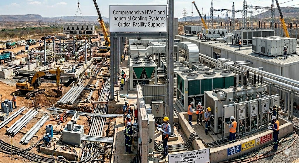
HVAC and Cooling Systems for Electrical Buildings
High-performance electrical equipment generates significant heat. A typical 138kV switchgear room produces 50-100 kW of heat, requiring precise cooling design.
Mechanical specifications for ventilation include:
- Battery rooms: 12 air changes per hour with hydrogen detection and explosion-proof exhaust fans
- Switchgear halls: 6-8 air changes per hour with redundant cooling units (N+1 configuration)
- Control rooms: Precision AC units with humidity control (45-55% RH)
- Emergency cooling: Automatic startup at 35°C ambient with diesel backup
Steel Structures and Gantries
The fabrication of gantries, support structures, and busbars requires precision mechanical engineering to ensure perfect alignment with both the civil foundations and the electrical terminals.
Steel structure specifications must include:
- Material grade: ASTM A36 or equivalent structural steel with a minimum yield strength of 250 MPa
- Corrosion protection: Hot-dip galvanizing (minimum 85 microns) or three-layer epoxy paint system
- Bolted connections: High-strength bolts (Grade 8.8 or 10.9) with torque verification
- Thermal expansion allowance: Slotted holes and expansion joints for temperature variations of ±40°C
- Wind loading: Design for 150 km/h wind speed (or regional code requirements)
Busbar and Connector Systems
The mechanical connection between transformers and switchgear is critical:
- Aluminum busbars: Lightweight, corrosion-resistant, require bi-metallic connectors for copper termination
- Copper busbars: Higher conductivity, heavier, requires silver-plated joints for low contact resistance
- Flexible connectors: Copper braids for vibration damping between the transformer and the rigid buswork
- Insulated bus ducts: For underground or confined space connections
For more details, read Whistleblower Engineers: Stories of Courage in Construction.
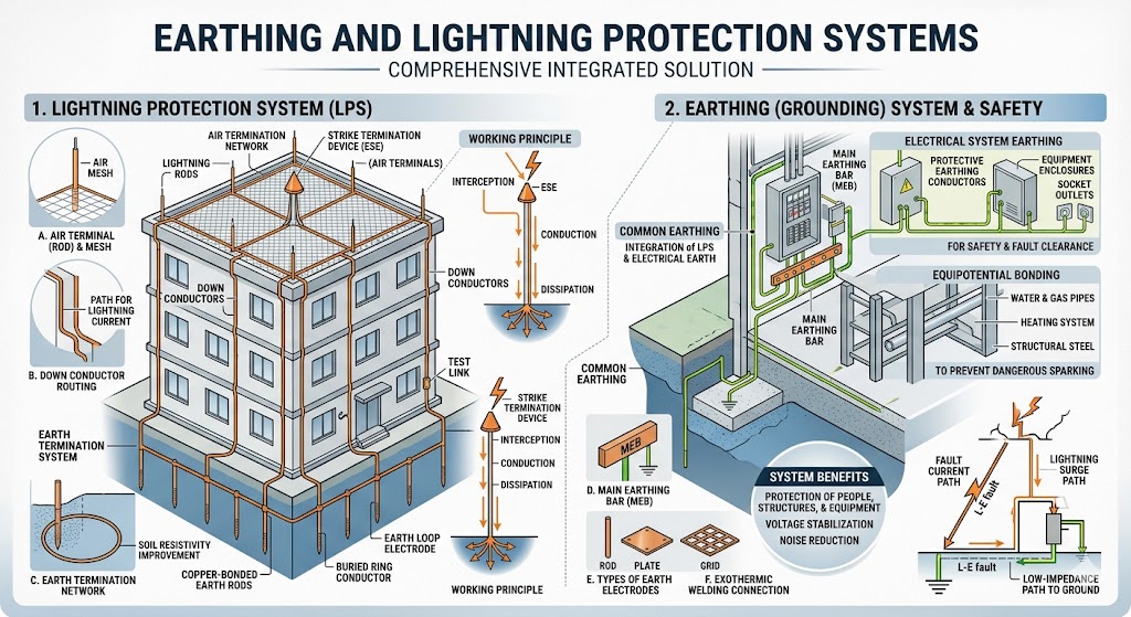
4. Earthing and Lightning Protection Systems
Often overlooked but critically important, earthing systems ensure the safety of personnel and equipment. A properly designed earthing system limits step and touch potentials to below 50V during fault conditions.
Earthing Design Parameters
- Earth resistance: Less than 1 ohm for grid stations, less than 5 ohms for industrial facilities
- Earth mat: Copper or galvanized steel conductors (minimum 70mm² cross-section) buried at 0.5m depth
- Earth rods: Copper-bonded steel rods driven to 3m depth, spaced at 10m intervals
- Chemical enhancement: Bentonite or marconite backfill in high-resistivity soils (>100 ohm-m)
Lightning Protection
- Franklin rods (ESE type): Placed at the highest points of the substation
- Shield wires: Stretched above busbars and critical equipment
- Surge arresters: Installed at transformer terminations and incoming lines (Type 1 and Type 2)
- Protection radius: Calculated using the rolling sphere method with a 60m radius
5. The Benefit of a Multi-Disciplinary Approach
Choosing a “Total Engineering” model — where Electrical, Civil, and Mechanical works are managed under a single specification framework — offers several key advantages:
- ✅ Elimination of Design Conflicts: Ensures that cable entries in civil drawings match the terminal locations on electrical equipment, preventing costly rework. Design conflicts typically cause 15-20% project delays.
- ✅ Streamlined Project Management: Reduces the “interface gap” between different teams, leading to faster commissioning and lower coordination costs by up to 25%.
- ✅ Enhanced Safety: A holistic view allows for better grounding (earthing) systems that span all three disciplines — electrical, civil, and mechanical.
- ✅ Extended Asset Lifecycle: Integrated design ensures that foundations, transformers, and support systems are mutually reinforced, not working against each other. Expected lifespan: 40+ years.
- ✅ Reduced Maintenance Costs: Properly coordinated designs reduce annual maintenance costs by an estimated 15-20%.
- ✅ Single-Point Responsibility: One contractor accountable for all engineering disciplines eliminates finger-pointing during troubleshooting.
Case Study: Successful Total Engineering Implementation
A recent 138kV grid station project in the Hudson Valley implemented Total Engineering Services with the following results:
- Zero design conflicts between civil and electrical drawings
- Project completed 2 months ahead of schedule
- 15% cost savings compared to separate contracts
- No interface-related failures in the first 18 months of operation
Learn from real-world experience: The GDAC Scandal: How Steel Theft Collapses Bridges and Love Under Construction: Romance on the Job Site.
6. Quality Assurance and Testing Protocols
No engineering specification is complete without defined testing and commissioning procedures.
Factory Acceptance Testing (FAT)
- Transformer: Turns ratio, insulation resistance, power factor, excitation current, resistance measurement
- Switchgear: Dielectric withstand, contact resistance, timing tests
- Protection relays: Point-to-point verification, logic testing
Site Acceptance Testing (SAT)
- Primary injection testing of CT circuits
- Secondary injection of protection relays
- Earth resistance measurement (fall of potential method)
- Thermal imaging scan under load (first 24 hours of operation)
7. Conclusion: Building the Infrastructure of Tomorrow
Building the infrastructure of tomorrow requires more than just high-quality components; it requires the intelligent integration of those components. By adhering to rigorous technical specifications across transformers, electrical apparatus, and civil-mechanical works, engineers can deliver projects that are built to endure the rigors of the modern world.
Whether you are designing a new 138kV grid station, upgrading an existing power substation, or developing an industrial complex, the Total Engineering Services approach ensures that every discipline works in harmony — from the steel rebar in the foundation to the copper windings in the transformer.
Remember: A transformer is only as reliable as the foundation it rests on, and the foundation is only as effective as the cables that connect to it. Integration is not an option — it is a necessity. Read our Exclusive Interview with Aryan: The Real Iron Sentinel for more engineering insights.
Final Word from Madina Construction Technologies: With 17+ years of experience in total engineering services, we have seen both the consequences of poor integration and the rewards of meticulous specification. Our team is committed to delivering projects where electrical, civil, and mechanical systems work as one.
🔗 Internal Resources (Madina Construction Technologies)
- 1. Why Structural Integrity Saves Lives
- 2. Grade-60 Rebar Specifications for Transformer Foundations
- 3. Using Thermal Imaging to Monitor Electrical Equipment
- 4. Whistleblower Engineers: Stories of Courage in Construction
- 5. The GDAC Scandal: How Steel Theft Collapses Bridges
- 6. Love Under Construction: Romance on the Job Site
- 7. Exclusive Interview with Aryan: The Real Iron Sentinel
🌐 External Standards & References (High Authority)
🔨 At Madina Construction Technologies, we deliver Total Engineering Services — Electrical, Civil, and Mechanical
Need expert specifications for transformers, electrical apparatus, or civil-mechanical works?
👉 Contact Our Engineering Team Today