
⚡ Grid Station Design to Commissioning – Complete Professional Guide by Madina Contech Lahore
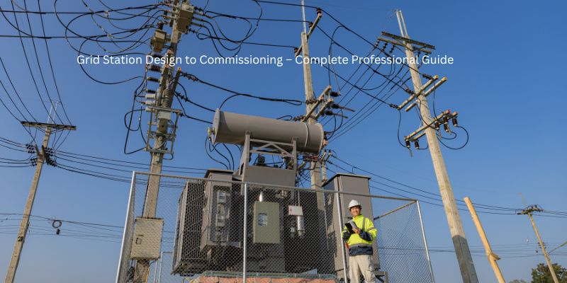
A grid station (also known as an electrical substation) is the backbone of any power distribution network. It transforms high-voltage electricity from transmission lines into usable voltage for homes, industries, and commercial facilities. Whether you are setting up a private grid for an industrial facility, a housing scheme, or a public distribution network, professional engineering execution is critical for safety, reliability, and longevity.
At Madina Contech Lahore, we bring 17+ years of expertise in high-voltage electrical engineering. This comprehensive guide walks you through the complete lifecycle of a grid station project – from the initial design phase to final commissioning and handover. For more information about our electrical engineering services, feel free to explore our service offerings.
📐 1. Design Phase: Engineering the Blueprint
Before a single brick is laid or a transformer is ordered, a comprehensive design must be developed using industry-standard tools like AutoCAD for civil layouts and ETAP (Electrical Transient Analyzer Program) for power system studies. This phase determines the success of your entire project.
We calculate the peak demand and future growth projections to determine the station’s optimal capacity (e.g., 132kV, 66kV, or 11kV). Proper load forecasting ensures your grid station remains adequate for the next 15-20 years. Under-sizing leads to premature upgrades; over-sizing wastes capital. Our team uses historical data and industry benchmarks to strike the perfect balance.
Creating a master roadmap that shows how power flows from the transmission lines through circuit breakers, disconnect switches, transformers, and finally to the distribution bus. The SLD is the DNA of your grid station. Every protection device, metering point, and control component is documented here. This document becomes the reference for all installation and maintenance work. IEEE Standard for Substation SLD Development provides additional technical guidelines.
Designing the physical arrangement and foundations for heavy machinery. Power transformers weigh several tons and require specialized RCC pads (Reinforced Cement Concrete) designed to handle dynamic loads. Oil collection pits with proper drainage are mandatory for environmental safety and fire prevention. Cable trenches, control room placement, and equipment access routes are all optimized during this stage. Madina Contech’s civil engineering solutions ensure your foundations last for decades.
Designing a deep copper mesh grid to protect equipment and personnel from lightning strikes, switching surges, and short circuits. A proper earthing system is non-negotiable for safety. We calculate step and touch potentials to ensure they remain within safe limits per IEEE 80 standards. The earthing grid includes a main ground bus, equipment grounding, lightning arrestors, and static grounding for fences.
Once the design is finalized, we move to our equipment procurement and quality assurance process to source only the best components.
🛠️ 2. Equipment Selection & Procurement
A grid station is only as strong as its core components. We source only IEC, ANSI, or local standards-certified equipment from reputable global and local manufacturers. Quality control begins at the factory and continues through delivery.
⚡ Power Transformers – The Heart of the Station
The power transformer is arguably the most critical (and expensive) component. We select units based on voltage ratio (e.g., 132/11kV), cooling method (ONAN/ONAF – Oil Natural Air Natural / Oil Natural Air Forced), impedance, and efficiency ratings (e.g., as per IEC 60076). Proper transformer sizing prevents overload and extends equipment life. Core construction (CRGO steel) and winding materials (copper vs. aluminum) significantly impact losses and longevity.
🔌 Switchgear & Circuit Breakers
SF6 (Sulfur Hexafluoride) or Vacuum circuit breakers are selected to “trip” and protect the system during fault conditions. Fast response time (measured in milliseconds) is critical to prevent equipment damage and arc flash incidents. We specify breakers based on short-circuit rating, interrupting capacity, and mechanical endurance. For a deeper understanding, refer to IEEE Guide for Circuit Breaker Selection.
📏 CT/PT Units (Instrument Transformers)
Current Transformers (CTs) and Potential Transformers (PTs) are essential for precise metering, protection, and monitoring. These devices step down high currents and voltages to measurable levels (typically 1A/5A for CTs and 110V for PTs) for protection relays, energy meters, and SCADA systems. Correct ratio and accuracy class selection ensure your billing and protection are both accurate.
🔋 DC Systems & Battery Banks
A reliable DC power system is the backbone of substation control. We install industrial-grade battery banks (typically 110V or 220V DC) with automatic chargers to ensure that even during a total AC blackout, the station’s control systems, protection relays, communication equipment, and emergency lighting remain fully operational.
Our team also provides comprehensive MEP solutions for industrial facilities, including grid stations.
🔧 3. Transformer Installation Protocol
Installing a large power transformer is a high-precision mechanical and electrical operation that requires experienced engineers, certified rigging teams, and strict adherence to safety protocols. Here’s our professional process:
Before the transformer arrives, we verify that the RCC foundation is fully cured (typically 28 days for full strength), perfectly leveled, and free of cracks. Even millimeter-level misalignment can cause vibration-induced damage over time. We also verify that anchor bolt locations match the transformer’s mounting dimensions.
Using heavy-duty hydraulic cranes with certified lifting capacity, we carefully position the transformer on its rails or foundation. This requires certified rigging engineers, load calculations, and safety zones. The transformer is lowered slowly and aligned precisely before bolting down. Rail-mounted transformers are rolled into position using temporary tracks.
Large transformers use specialized mineral oil or ester fluids for cooling and electrical insulation. We perform vacuum filling and hot oil circulation to remove moisture, dissolved gases, and particulate matter. Moisture is the #1 enemy of electrical insulation – it reduces dielectric strength dramatically. Our oil processing units achieve moisture levels below 10 ppm and dielectric strength above 75 kV.
Careful installation of high-voltage bushings (porcelain or composite), cooling radiators, conservator tank, breather, Buchholz relay, and temperature indicators. All gaskets are checked for proper sealing to prevent oil leaks. Leak detection tests are performed before energization. We also install all control cabling from the transformer’s local control cabinet to the main control room.
Proper transformer installation directly impacts the energy efficiency and longevity of your electrical assets. Our team ensures every detail is addressed.
🧠 4. Protection & Control Systems – The Brain of Your Grid
A modern grid station needs an intelligent “brain” to monitor, control, protect, and communicate. Without proper protection, a small fault can cascade into a major blackout or equipment destruction.
📟 Protection Relay Panels
Installation of numerical/microprocessor-based protective relays that detect overcurrent, earth faults, differential faults, over/under voltage, over/under frequency, and distance protection. These relays send trip signals to circuit breakers in milliseconds (typically 30-80 ms). We configure relay settings based on coordination studies to ensure selective tripping – only the faulty section is isolated, keeping the rest of the system operational.
💻 SCADA Integration & Remote Monitoring
Connecting the station to a central monitoring room (and even remote locations via VPN) so operators can control the grid remotely. SCADA (Supervisory Control and Data Acquisition) enables real-time data visualization (voltages, currents, power, breaker status), alarm management, event logging, historical trending, and remote control of breakers and tap changers. This reduces response time during emergencies and minimizes site visits.
🔋 Station DC System & UPS
Installing redundant DC battery banks (typically 110V or 220V) with automatic chargers and a separate UPS for sensitive electronics. This ensures that even during a total AC blackout, the station’s control systems, protection relays, communication equipment, SCADA servers, and emergency lighting remain active for hours. Regular battery testing and maintenance are part of our comprehensive service.
📡 Communication & Teleprotection
For interconnected grids, high-speed communication links (fiber optic or PLC – Power Line Carrier) are essential for transfer trip schemes and remote data exchange. We install and commission these systems to ensure seamless coordination with the utility’s network.
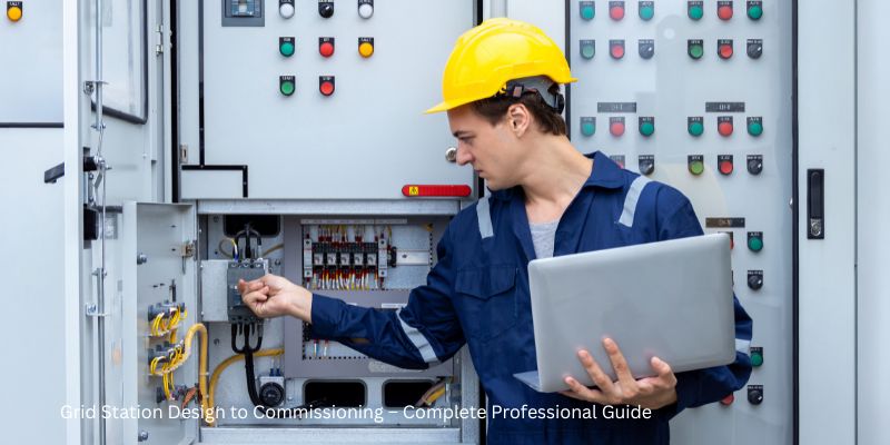
✅ 5. Testing & Commissioning – Before You Energize
Before “energizing” the station (applying full voltage for the first time), we perform a rigorous battery of tests to verify every component, connection, and setting works as designed. Commissioning is the final quality gate.
📏 Insulation Resistance (Megger Test)
Performed on all cables, windings, and busbars to ensure no leakage path exists between conductors and ground. Low insulation resistance indicates moisture, contamination, or damaged insulation. We test at voltages appropriate for the equipment rating (e.g., 5kV megger for 11kV systems).
🔄 Turns Ratio Test (TTR)
To verify that the transformer is stepping voltage up or down correctly according to its nameplate ratio. Ratio errors indicate winding problems (shorted or open turns), incorrect tap changer position, or internal misconnections. We perform this test on all tap positions.
🛢️ Oil Dielectric Strength & Dissolved Gas Analysis (DGA)
Oil samples are tested for dielectric strength (breakdown voltage) and subjected to DGA to detect incipient faults. High moisture or gas levels indicate problems that must be addressed before energization. This is the single most informative test for transformer health.
⚡ Primary & Secondary Injection Tests
Primary injection: Injecting actual high current through CTs using a primary injection test set to verify CT ratios, polarity, and complete protection scheme operation, including breaker trip times.
Secondary injection: Injecting simulated signals into relay terminals to verify relay logic, setpoints, timers, and communication outputs. This ensures every protection function works correctly.
🔌 Circuit Breaker Timing & Contact Resistance
Measuring opening and closing times, contact travel, and dynamic contact resistance to ensure the breaker operates within manufacturer specifications. High contact resistance leads to overheating and potential failure.
🧪 Vector Group & Polarity Check
Verifying the transformer’s vector group (e.g., Dyn11) and polarity before parallel operation with other transformers. Incorrect vector grouping leads to catastrophic circulating currents.
📡 SCADA & Communication Point-to-Point Check
Every analog value (voltage, current, power) and status point (breaker position, alarm) is verified from the sensor to the SCADA screen. Control commands are tested from SCADA to the field device. This is tedious but essential for reliable remote operation.
After all tests are passed, we perform a controlled energization – first at no-load, then gradually loading the station while monitoring all parameters. For ongoing reliability, consider our annual maintenance contracts (AMC) for electrical systems.
📊 Phase Summary: Professional Standards at a Glance
| Phase | Key Activities | Our Professional Standard |
|---|---|---|
| Design | Load flow, SLD, Earthing, Layout | Precision AutoCAD & ETAP, Structural Load Calculations |
| Equipment | Transformer, Switchgear, CT/PT, DC System | IEC/ANSI certified, Factory-witnessed testing |
| Installation | Foundation, Rigging, Oil filling, Assembly | Vibration-resistant foundations, Vacuum oil filtration |
| Protection | Relays, SCADA, Battery, Communication | Numerical relays, Redundant DC, Remote monitoring ready |
| Commissioning | Megger, TTR, DGA, Injection tests, SCADA check | Certified test equipment, Detailed commissioning reports |
🏢 Why Madina Contech for Your Grid Station Project?
Build with Engineering Certainty. Whether you are setting up a private grid for an industrial facility, a residential housing scheme, or a public distribution network, Madina Contech provides the 17+ years of expertise, technical depth, and project management discipline required for high-voltage execution.
- ✅ IEC-Compliant Designs – International standards for safety, reliability, and future-proofing
- ✅ End-to-End Service – From feasibility study and design through procurement, installation, testing, commissioning, and annual maintenance contracts (AMC)
- ✅ Certified & Experienced Engineers – Proven track record with 132kV, 66kV, 33kV, and 11kV substations
- ✅ Quality Assurance – All tests performed with calibrated, certified equipment; detailed reports provided
- ✅ Timely Delivery & Budget Control – Structured project management ensures on-time, on-budget completion
- ✅ Local Presence, National Reach – Based in Lahore, serving clients across Pakistan
📞 Free Technical Consultancy for Your Grid Project
📍 Lahore, Pakistan | Serving All Pakistan
Call / WhatsApp for immediate discussion:
📧 info@madinacontech.com | 🌐 madinacontech.com
Mention “Grid Station Article” when you call to avail this offer.
📝 Final Word: Your Grid Station, Engineered for Life
A grid station is not just equipment on a concrete pad – it is the lifeline of your electrical infrastructure. Every component, from the transformer core to the smallest protection relay, must work in perfect harmony. Cutting corners during design or installation leads to costly failures, safety hazards, and operational downtime.
Madina Contech Lahore brings engineering certainty, decades of hands-on experience, and a commitment to quality to every grid station project – whether a small 11kV industrial substation or a large 132kV grid station.
For free technical consultation, site visit, or a no-obligation quote for your upcoming grid station project, call us today at +92 322 9969786 or email info@madinacontech.com. Let’s build your power infrastructure the right way – from design to commissioning and beyond.